Agentlien - Graphics Programmer
Anatomy of a Texture
Introduction
Last year I had to write code which converted texture data between gaming platforms. Going into it, I seriously underestimated the complexity of texture memory layouts.
I'm currently working on a team at 505 Games porting a custom PC game engine to consoles. One of the many challenges faced has been around texture conversion. I knew there were a lot of complexities and subtleties to it. I recognized most of them in isolation. But, it wasn't until I had to write working code which handled all these details in tandem that the full complexity really sank in. And so, I thought this would make for an interesting blog post!
This blog post will explain the complexity of texture memory layout, along with why it is necessary. This will be done through the lens of someone trying to debug the calculation of memory addresses for each part of a console texture. Due to the subject matter, this post will have to get a little bit more technical.
I will assume an understanding of programming fundamentals, memory layouts, as well as familiarity with basic video game technology and digital imagery.
Throughout this article we'll use a 1024x1024 RGBA texture using BC7 as an example. For illustration purposes, let's use a simple wood texture.
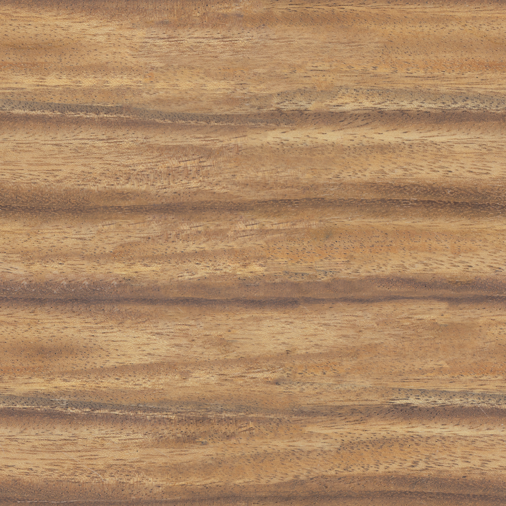
Converting this texture between platforms requires us to keep track of a lot of details. For the purpose of this article I will explain the following: block compression, texel ordering, mips, and texture tiles. There are other details such as pitch, depth, and texture array index. These mainly require simple offsets which are slightly annoying but do not add any interesting theory, so I will ignore them.
Here is what that image would look like if we ignore all of these complications and interpret the result as a simple stream of color values:

Platform specifics
If this post is about texture formats, why am I talking about memory locations? All the details we will go through have some very important similarities and distinctions between platforms. In particular, textures are decomposed into the same hierarchy of building blocks across platforms. However, at every level of the hierarchy the order of these elements in memory may differ between platforms. This means that given a memory area to hold the texture, the act of converting a texture between platforms can be seen as a problem of calculating, for each of these elements, its expected memory address after conversion.We will primarily discuss most of these components in a platform-agnostic way. Where a distinction is necessary, we will rely on the view taken by DirectX 12.
Idealized view
Given a general understanding of digital images, how might one expect a 2D texture to be represented in memory? Images have a number of color channels, each having a specific bit depth. A common bit depth is 8, meaning one byte per channel. This gives us values in the range [0,255] per color. An image comprises a grid of color samples, typically across two dimensions: width and height. For ordinary images these samples are called pixels. For textures we call them texels. Given this, the naive assumption would be that an RGBA image with 32-bit color depth is just a stream of texels sweeping from left to right, row by row, with each texel represented as four consecutive bytes: one for each channel. While some simple textures really do work this way, this is unfortunately very far from how most textures are represented in modern video games.The reason is performance. There's a number of orthogonal techniques applied, each of which complicate texture representation but improve rendering performance. Most (e.g. texel ordering & texture tiles) exist to improve cache locality. That is, doing our best to store data as close as possible to all other data we expect to need at the same time. Good locality drastically decreases the amount of time wasted waiting for memory transfers - which is one of the most expensive operations in modern computer hardware. While block compression also helps with locality, it primarily improves memory transfer speed by decreasing texture size in memory. Finally, we have mips which drastically reduce rendering cost by downsampling the entire texture in multiple steps ahead of time - allowing us to avoid the many expensive texture samples we'd otherwise need any time we want to average all texels in a surrounding area.
From the perspective of someone debugging texture loading across platforms, every one of these techniques is another wrinkle to keep track of.
A single texel
Let us take a look at how an actual texel is represented in a typical modern video game texture. For simplicity, let us assume the original image is RGBA with 8 bits per channel as above. This gives us a total of 32 bits (4 bytes) per texel if uncompressed. However, most modern textures use block compression. Block compression shrinks the memory size of textures to decrease data transfer times.
The most common block compression format these days is BC7. This is a very complex format with more quirks than I can explain in this article - I don't even know them all in detail. At its core, BC7 is a lossy compression format leaning on clever assumptions about similarity of adjacent texels. It stores texels in 4x4 blocks. Each block specifies pairs of reference colors called end points. Each texel then gets its color by specifying an index identifying an interpolated value between these end points. A single block is 16 bytes large and describes 16 texels - which amortizes to a single byte per texel; a compression factor of 4x for an RGBA texture with 8-bit channels. Despite this large compression factor it is very hard for the human eye to tell the difference between BC7 compressed textures and uncompressed textures - even in side by side screenshots. This is great news for game developers who need to optimize streaming of large numbers of big textures. Another advantage of compressing texels in blocks is that a lot of effects require sampling multiple adjacent texels. Making nearby texels closer in memory increases cache locality and speeds up memory access.
Here you can see what our above texture looks like if we correctly treat our texture as a series of 16 byte chunks each representing a 4x4 BC7 block. We can now see blocks of the correct colors, though out of order.
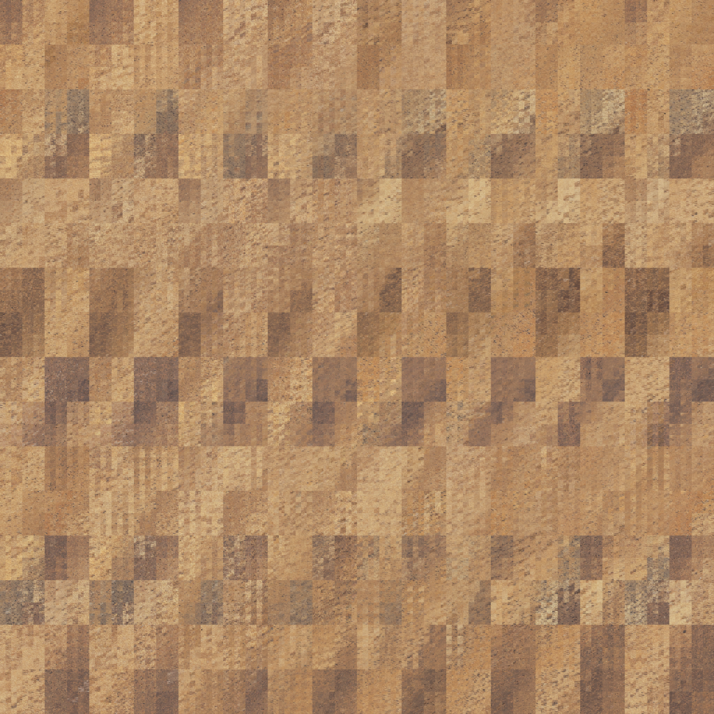
Code which would otherwise read/write a single texel now has to check whether to deal with a texel or block. For non-compressed textures width and height are just an index across each dimension. Compressed textures need to iterate across blocks of 4x4 texels at a time. Compression also affects how to calculate the size of a texture in memory. Memory size depends on resolution, number of channels, channel bit depth, and potential compression mode.
Debugging a block
The amount of clever tricks employed by BC7 is bad news for debugging. It makes a memory dump practically inscrutable without tooling. Graphics debuggers contain built-in tools to visualize and analyze textures. Unfortunately, that often doesn't help when the result looks like the above figures. It is also non-trivial to write visually interpretable debug information to a compressed texture. If you write raw values ignoring compression you'll get a mess of meaningless colors.
What really complicates visual debugging is that any accidental offset which changes your byte alignment renders all data visually incoherent. This is because it affects which parts of the blocks are read as end points and which are interpreted as indices. If you write debug information because you have a problem with your texture address computations it can even be a challenge to find where this information ended up.
Luckily, I found a few useful tricks for debugging.
In most cases, you can simply replace each 16 byte block (128 bits) with 4 separate 32-bit integers of your choice. For instance, this is just enough to store x, y, z coordinates and mip level. That way, you can easily identify the exact memory offset by reading the memory dump of any given texel block and comparing its written values to the actual coordinates.
In some cases I needed to write larger chunks of data to specific texture locations matching some debug criteria. In these cases you can write 16 bytes of all zeroes to get a block of 4x4 texels which is technically invalid but guaranteed to render as black. I've been using a series of black blocks as visual markers. Just enough to get a few visible blocks even with alignment issues. Between these markers I write my raw debug data values. This way I can visually identify debug portions in a texture view, find the memory location of the corresponding texel, then use memory dumps to read the actual values between the markers.
Texel ordering
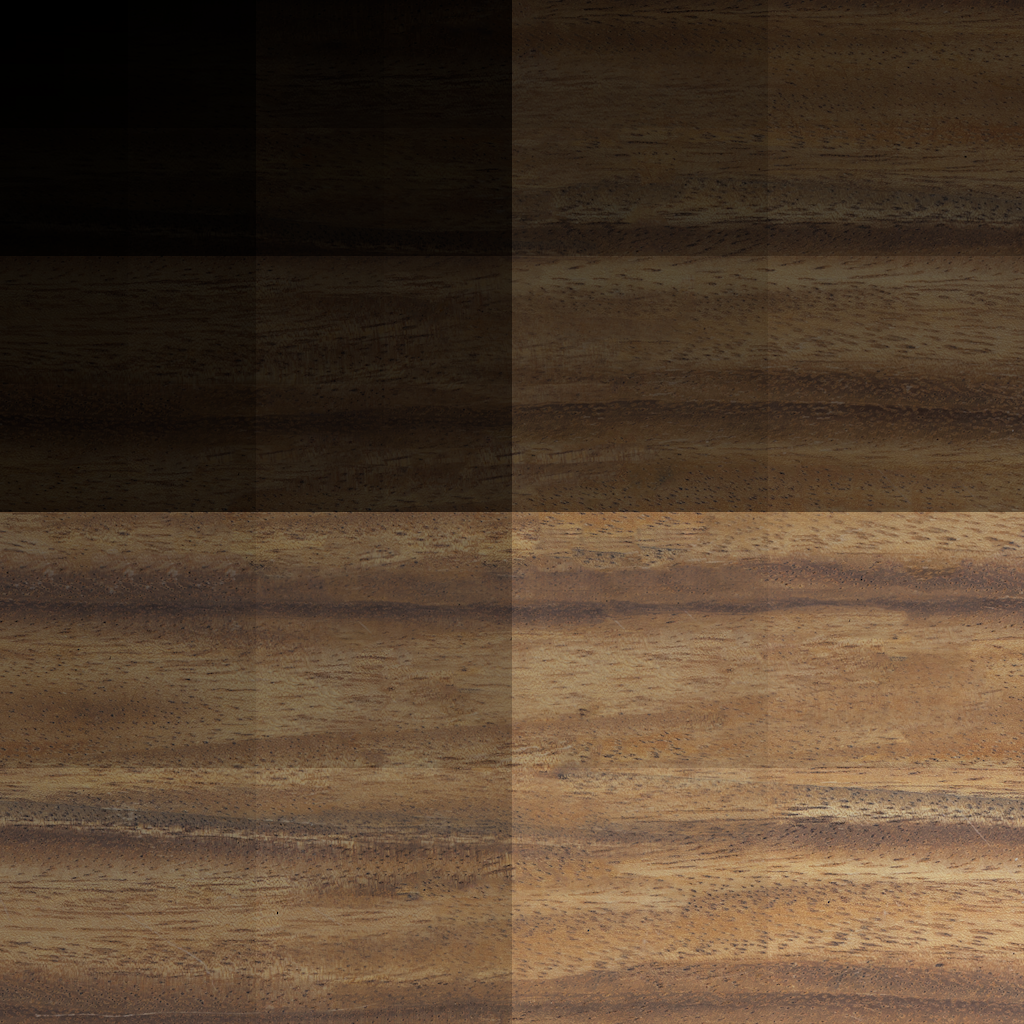
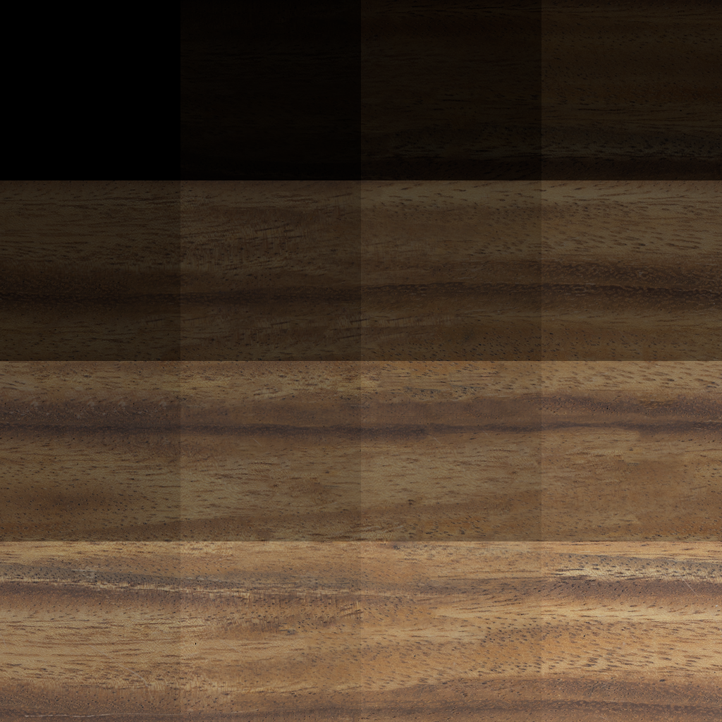
It's easy to imagine texture memory as a byte stream sweeping texel by texel, row by row. Unfortunately, such a layout is not ideal. We want to do everything we can to increase locality of neighboring texels. That is, texels which are visually close to each other should also be close in memory. This matters because nearby texels will often be sampled together. To that effect, textures often use different memory layout patterns. Such a pattern is called a swizzle. When iterating over all texels in a texture, the swizzle allows you to transform a texel index to the coordinates of the corresponding texel. The most well-known swizzle is probably the Morton order. This swizzle means the order of texels in memory isn't left to right, row by row, but rather moves in a fractal Z pattern across the texture. Use the slider to see the difference. The left and right view show the same image each multiplied by a linear and z-ordered mask respectively. Meaning that 4x4 texel elements go from black toward their original color as their index increases.
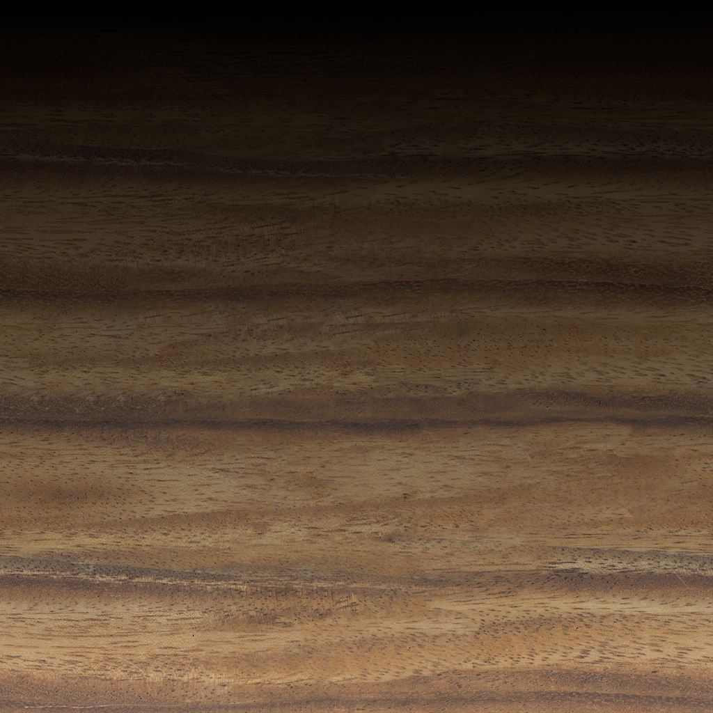
There are other possible orders, and which one is needed depends on the details of your specific texture. This choice may also differ for the same texture across platforms. Meaning you may need to completely re-order the texels when converting a texture from one platform to another. In the general case, your conversion code has to take into consideration both which ordering is used for the source and target platform.
As with block compression, this re-ordering makes debugging more complex than it already is. Correctly aligned texture memory using the wrong swizzle will make your image look like 4x4 puzzle pieces all jumbled up. See Figure 3 above.
All of this is getting quite complicated, but with a bit of grit we can sort it out. Of course, it gets worse.
Mips
Textures aren't actually single images. Each texture contains a series of increasingly scaled down versions of the same image, called mips. The largest version (mip 0) has the size of the original image. Each consecutive mip is half the width and height of the previous one. The reason for this is that when rendering, we want the resolution of sampled texels to match the resolution of the render target. For a textured surface further from the camera, each pixel will overlap several texels. This means we need to sample a larger area of the texture, which is relatively expensive. Not doing so will cause aliasing artifacts such as shimmering and Moiré patterns. The solution is to create mips ahead of time. When rendering a textured surface the shader can then use the mip where texel size most closely matches the render target pixel size. Real-world renderers use more advanced texture filtering techniques, but they all rely on mips to precompute area sampling.
Mips are largely laid out in well-defined order one after the other in memory. However, whether they are stored in ascending or descending order varies between platforms. This means you cannot simply iterate over them and increase both source and destination pointer in lockstep. For each mip you need to figure out where in memory it starts for the source and target platform.
Tiles
The next complication is tiles. Again, we want to optimize cache locality when working on a texel and its surroundings. Another way this is done is by splitting texture memory into tiles. These tiles each hold a square piece of the underlying mip. This layout also allows games to stream only the visible parts of large textures. Within each tile, adjacent texels are block compressed and swizzled as described above. Tiles are laid out linearly in memory from top left to bottom right. A tile is typically 64KiB. This means a 1024x1024 texture mip using BC7 is made up of 16 tiles in a 4x4 grid, with each tile containing a 256x256 texel square. With BC7, each tile contains 4096 blocks of 4x4 texels each, laid out according to whatever swizzle pattern we're using.
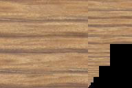
Thinking of how to store this in memory, it's easy to consider a hierarchical view as described above. Textures are made of mips. Mips are made of tiles. Tiles are made of blocks or texels. Of course, the smallest mips will be much smaller than a full tile, so giving them a full tile each would be very wasteful. For our example texture we could fit the last 8 mips in a single 64KiB tile! Doing this for every texture the memory savings quickly add up. Hence, most platforms pack all mips smaller than a full tile into as few tiles as possible. This is called the mip tail. In fact, figure 5 shows precisely the 256x256 mip which fills a single tile next to all higher mips, showing that together they fit in a single packed tile.
This means we need to handle both mips spanning multiple tiles and tiles containing multiple packed mips.
Non-contiguous tiles
While everything above is nearly sufficient to convert a contiguous linear texture to console specific memory layout, there is a final wrinkle. In a modern game engine textures are often streamed tile by tile into a shared area of texture memory (called a heap in DirectX12). Each tile of a texture is mapped to its own memory area within this heap. With different mips getting streamed in and out on demand we may get fragmentation of texture memory. This means different tiles of a texture may not end up in a contiguous area of texture memory. Which in turn means if we are writing data to texture memory we need to create a translation from tile index of a texture to the specific address where this tile is mapped. Then we add an offset within the given tile to get actual memory address. A simpler take would be to base our calculations on the base address for the first texel of our texture plus a global offset. But for non-contiguous textures this would overwrite tiles from other textures and in turn leave some of our own tiles uninitialized. This is similar to an actual bug I caused during this project, and it took me quite some time to realize the faulty assumption!
Summary
Combining all of these gives you a rough view of how a texture is laid out in memory and how it may differ between platforms. Putting it all together in my conversion code took surprisingly much work. Along the way I kept bumping into special cases and specific textures which broke implicit assumptions I'd made. Hopefully, you can now share my appreciation for this aspect of the complexity which goes into making your games run just a little bit faster.
About the author

Hello,
My name is Daniel "Agentlien" Kvick and I'm a Graphics Programmer with a passion for games.
I currently work as a Senior Software Engineer at 505 Games.
Here you'll find a selection of things I have worked on.